Reverse Osmosis Water Purification Process
The use of a Reverse Osmosis System is a common water purification process for large filtration systems. Commercial and industrial water filtration systems will often utilise a reverse osmosis process to ensure high compliance with water testing. The inner workings of a reverse osmosis system can be a difficult process to understand. This page will cover what the process entails, how it works, and the areas where a reverse osmosis system is most effective. We have also included a list of common terminology as well.
What is Osmosis
Osmosis is a process common in biological systems. It results in water from a dilute solution that passes through a semi-permeable membrane into a more concentrated solution on the other side. Energy is released in the process. This is counterproductive to the requirements of desalination where we require the reverse to occur, i.e., we need freshwater to pass out of the concentrated solution and accumulate on the other side of the membrane where we may collect and utilise it. A reversed process needs the input of energy. The process is called reverse osmosis, commonly abbreviated to R.O.
What is a Reverse Osmosis Water System?
A Reverse osmosis system achieves separation of dissolved salts and impurities from water solutions via a sediment filter, using pressure exerted on a semi-permeable membrane. The passage of dissolved materials (solutes) through the membrane is resisted. The membrane materials chemical structure, though, allows the potable water to permeate through relatively easily. Salts, along with other impurities that build up on the feed side of the membrane, are continuously flushed away. This is a more concentrated solution called the Concentrate or Reject. The purified water called the Permeate is meanwhile drawn off for use.
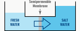
The diagram below shows a simplified reverse osmosis system vessel with two compartments separated by a semipermeable membrane. On one side of the membrane, we have potable water or a very dilute solution. A more concentrated salt solution is on the other side.
Through the semi-permeable membrane, water will pass into the concentrated solution from the purer solution. The level will increase on the right and fall on the left.
You place a limp lettuce leaf into cold water to make it crisp. The freshwater from the outside permeates through the leaf cells natural semi-permeable membrane into the slightly salty solution inside the cell. The pressure in each tiny cell makes it taut, and the leaf becomes crisp once again.
Osmotic Pressure
Let us consider where seawater, containing 36,000 ppm of salts, is in the right-hand compartment and potable water in the left. In a short time, the gauge would register pressure of about 2600 kPa (i.e. about 360 psi) on the gauge. It may be hard to visualise, but this pressure would, in fact, develop spontaneously in the apparatus shown, and so we say that the osmotic pressure of seawater is about 2600 kPa. If we wanted to produce fresh water from the seawater in this apparatus, we could mechanically apply more than 2600 kPa to the right-hand chamber to push the freshwater out of the seawater through the membrane. In fact, a typical reverse osmosis system, a seawater desalinator, in particular, uses 5-7000 kPa (i.e. up to 1000 psi) to do just this. Excess pressure over the osmotic pressure is used to overcome the membranes natural flow resistance.
Practically, the osmotic pressure of saltwater may be regarded as directly proportional to the salt concentration. It means if the seawater in the above illustration were diluted 50/50 with fresh water, the osmotic pressure would fall to 1300 kPa or half that of undiluted seawater. Conversely, the osmotic pressure doubles when the concentration of salt doubles. Therefore the lower the salt content of the water, the easier it is (i.e., the lower the pressure required) to desalinate it.
Configuration of Practical Reverse Osmosis Systems
General Flow Schematic
The process described previously would not be a practical proposition, as the salt concentration would quickly rise in the right-hand chamber (see fig. 3) due to the freshwater passing out to the left and leaving the salt behind. This would lead to higher osmotic pressure to be overcome by the piston to sustain the flow. The process would quickly stop when the osmotic pressure reached the applied pressure.
One could stop the process, empty the concentrated seawater and replace it with more untreated seawater before repeating the procedure. This would be a cumbersome process, and in practice, reverse osmosis is conducted as in figure 4.
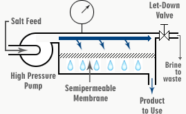
FIG. 4. SCHEMATIC OF REVERSE OSMOSIS DESALINATION PROCESS
Saltwater is supplied to the reverse osmosis system via a high-pressure pump as Feed Water (F). From here, it is forced through the chamber (C) and out through the let-down value (L), which is set to maintain the necessary operating pressure of the system. In seawater desalination, we would adjust this valve to maintain about 6000 kPa in chamber C.
When passing along the chamber (C), some of the water goes through the membrane into the chamber (P) as the desalinated product (permeate). This leaves the salt behind. The salt concentration of the feed water increases as it passes from (F) to (L), from where it is continuously directed to waste. It carries the concentrated salts and impurities with it. This flow is called either the Concentrate or Reject.
The actual proportion of freshwater removed from the saltwater feed depends on the design of the reverse osmosis system itself. The type and quality of the saltwater being processed are also factors. Recovery Ratio is the ratio of the permeate flow rate to the feed flow rate. It varies from about 20% to 80%.
Some Important Terms
Before proceeding, you should become familiar with the following terms, which are used fairly consistently in regards to reverse osmosis systems:
PERMEATE
The desalinated water is called the permeate because it has permeated through the membrane. Also called PRODUCT.
CONCENTRATE
The discharge to waste is called the concentrate because it has been concentrated as it passes along the chamber (C). This discharge is also called the REJECT.
FEED
The flow entering the membrane from the high-pressure pump is called the feed.
SYSTEM PRESSURE
The system’s operating pressure, the pressure inside the chamber (C), is called the system pressure. It is also sometimes called the feed pressure, but this is confusing as feed pressure is more commonly applied to the pressure BEFORE the high-pressure pump.
LETDOWN VALVE
The valve (L) is called the letdown valve because it is here that the system pressure is “let down” to atmospheric pressure again.
RECOVERY RATIO
The ratio of permeate flow rate to feed flow rate is called the recovery ratio because it denotes the proportion of product water recovered from the feed. It is usually expressed as a percentage.
REJECTION RATIO
This is the percentage reduction of salt in the permeate concerning the feed supply. For example, a permeate of TDS 200 from a feed supply of TDS 10,000 would be referred to as a rejection of 98%. It is dependent on both the membrane itself and the RO system design in general.
Membrane Configurations
Spiral Wound
The first question that may spring to mind is, how does the thin semi-permeable membrane within a reverse osmosis system withstand the high pressures we have been considering? Several different techniques have been used to do this. Still, at this stage, we will consider in detail only the most common configuration presently used, the Spiral Wound configuration.
It is perhaps easiest to visualise the spiral wound configuration by considering the membrane material as a sheet having been made into a bag, similar to an ordinary plastic bag but with a lip like letter envelope. Consider now a sheet of thick, porous fabric inserted into the bag and the lip sealed around a tube that contains several small holes drilled in it as in fig. 5.
Imagine the entire representation depicted in fig. 5b is now being placed into a pressure-resistant closed box with the ends of the permeate tube protruding from and sealed into the box wall. If we were to now pump saltwater into this box, we can see that the water would exert equal pressures on both sides of the membrane bag to be evenly supported. Permeate would pass through the membrane into the porous permeate carrier and flow through the carrier to the permeate tube. It would then pass through the perforations in the tube and out of the box through the permeate tube itself.
Because such a configuration would require a lot of space and a large pressure vessel, the representation of fig. 5b is rolled into a spiral, something like a Swiss roll, so that a cylindrical pressure vessel can be used compact and relatively cheap. A sheet of coarse mesh is rolled up to act as a spacer and prevent the two membrane surfaces from coming into contact and restricting water flow. The result is depicted in figure 6; the space between the membranes in which the mesh spacer lies constitutes the schematically represented chamber (C) in figure 4.
The concentrate spacer also acts to promote turbulence in the feed flow, which tends to discourage the deposition of scale and other fouling materials on the membrane surface.
Turbulent Flow
Turbulent flow over the membrane is also important for another reason. As we have seen, removing the freshwater from the feed results in a concentration of the salts in the remaining solution. This concentration is most pronounced at the membrane surface, as this is the area reverse osmosis systems where the desalination process occurs. This means that the membrane is called upon to desalinate water of higher salinity than is necessary. Turbulence helps to disperse this concentrated layer into the more dilute bulk of the feed flow.
Using this general configuration, large surface areas of the membrane can be formed relatively cheaply into the membrane elements. Several of these elements can be fitted into a pressure vessel made of fibreglass pipe, which is corrosion resistant and strong. The most common size for these elements is 4 inches diam. And 40 inches long. They are also available in 2.5, 6, 8 and 11-inch diameter sizes.


